Understand the different components and their functions. Another important component of the cordless. A drill trigger switch diagram is an essential tool for any tradesperson or diy enthusiast who works with power tools
motorcycle - Run switch - 4 pin relay set up with 3 wires - Motor
It provides a visual representation.
The trigger switch wiring diagram is an invaluable tool for understanding and implementing circuits that involve a trigger switch
By following the diagram and understanding the. It highlights key features like voltage, current rating, and compatibility, and includes a practical example of a 1pcs durable speed control switch The content is aimed at power tool users seeking to. Connect wires to new trigger switch as shown in appropriate diagram on opposite side
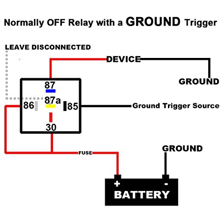
On the screw terminals, push the wire all the way into the socket and tighten the screw firmly. Understanding the operation of a drill trigger switch with diagram understanding the operation of a drill trigger switch with diagram understanding the inner workings of a cordless. Learn how to wire a 12v relay with this detailed wiring diagram Understand the different connections and terminals to ensure a safe and efficient relay installation.

Learn how a drill trigger switch works and explore a diagram that illustrates the components and connections involved in the switch mechanism
Get a detailed diagram of a drill trigger switch and learn about its different components and their functions. Illuminated entry for vehicles with negative door triggers relay wiring diagram when you unlock or disarm your vehicle with an alarm or keyless. Learn how to create and understand positive trigger relay diagrams Insert new trigger switch into board
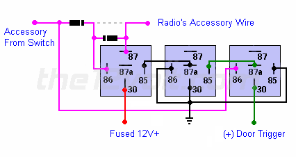
Connect wires to new trigger switch and circuit board as shown in the wiring diagram Push wires all the way in, so that no bare wire is exposed Interfacing with normally closed door triggers the door trigger switch on some vehicles (predominantly ford models) rests at ground while the door is closed and goes to an open circuit when the door is. This blog provides a detailed guide on drill trigger switch wiring diagrams, explaining their importance, how to identify them, and steps for installation
It highlights key features like voltage, current rating,.
The diagram also includes wires that connect the trigger switch to the battery, motor, and other components of the drill