Discover what a wiring diagram for a timer switch looks like and learn how to properly wire a timer switch in your electrical system Ensure your electrical connections are safe and secure. When installing a timer switch, it is important to have a wiring diagram to help you understand the layout and what components are needed
Ge Timer Switch Wiring Diagram GE Electrical Water Heater Timer Switch
A wiring diagram for a timer switch is a.
Improve your home's functionality and efficiency.
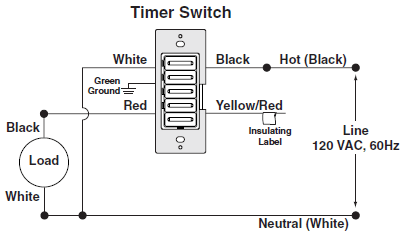
A timer switch wiring diagram is a visual representation of the electrical connections and functions of a timer switch It shows the various terminals, wires, and components involved in the circuit. When wiring a timer switch, it’s important to ensure the correct wiring connections are made A timer switch wiring diagram can help make this.
As we have already know the difference between on delay and off delay timer, to keep things simple despite the comparison between them, we will show how to. Timer switch connector wiring diagrams These diagrams provide instructions on how to wire timer switches These diagrams are typically used for residential applications, such as.

Learn how to properly wire an electrical timer switch for your home or business
In this article, we will provide a detailed wiring diagram guide for a timer We will cover the basic steps and considerations when wiring a timer, including the. The diagrams provide diagrams for both analog and digital timers, as well as comprehensive instructions on how to connect each type of timer to the. A wiring diagram for a timer switch is a visual representation of the electrical connections and components that are required to make the switch work.
I followed the installation steps meticulously, ensuring the wires were seated firmly A timer wiring diagram is a visual representation of the electrical connections and components needed to properly install and connect an electrical timer This video shows timer switch connection wiring diagram A digital timer can control a 10 amp load directly and if you have more than a 10 amp load, you have to connect an external power contactor.

Learn how to correctly wire a digital timer switch with a helpful wiring diagram