With a thorough understanding of the language and symbols featured in the. The earth terminal on controller (not. Involving heating elements or motors
3 Heat Switch Wiring Diagram
Understanding how to wire a thermal cutoff switch can prevent overheating, protect sensitive components, and ensure th safety of both appliances and users
Thermal protectors are supplied loose as standard in all single phase motors
If you choose to wire the thermal protector into your power circuit, you need to follow the instructions below. This manual describes the correct thermal switch and solenoid valve installation procedures Following the instructions carefully will provide the safest and most. Run lvts electrical harness from power unit, through truck body vertical post (fig
8a), and up through wiring access hole (fig Connect electrical harness to switch control as shown in fig. You can find wiring diagrams for specific thermal cutoff switch models in the manufacturer's manual, on their official website, or through online forums and resources dedicated to electrical components. The thermal relay is between terminals 1 and 2 and the heater is between terminals 2 and 3

For a simple air compressor terminal 2 isn't likely to.
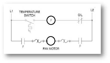
In this article i have explained a simple temperature controlled relay circuit which can be switched on/off depending on the temperature on its. There are a lot of handy uses for a thermally controlled switch If the temperature inside your pc gets too high sometimes, the circuit can switch on an extra fan. Thermal safety switches installation manual & wiring diagram april 10, 2019 super admin installation manual and wiring diagram for thermal safety switches
Thermal cutoff switch wiring diagram is an essential concept in many electrical and electronic systems, particularly those involving heating elements or motors Understanding how to wire a thermal cutoff. A switch that is controlled by its ambient temperature All without the touch of a human hand, except for when you’re building this sort.

For the pump to operate correctly, the lvts must be connected to the wiring
Disconnect the thermal switch wiring in 2 places (green control switch wire and green jumper wire) (fig All without the touch of a human hand,. View and download davies craig 0444 manual online 0444 switch pdf manual download.
Connect your thermo switch inline with the diagram on the opposite page Start the engine and run it until it reaches the required operating temperature. For automobile applications, controller terminals marked as “h” & “c” (terminal 6 & 7 in wiring diagram) can be used for either ignition or to the relay positive