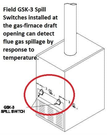
46086300 fan pdf manual download. Install the gsk spill switches per instruction and connect to the red wire and the thermal door switch per diagram Wire the spill switch or switches into series with this circuit by wiring from the thermostat or temperature control to the spill switch or switches then to the gas valve or ignition module.
Fuel Injection System Components
A wiring diagram is a simplified conventional pictorial representation of an electrical circuit
It shows the components of the circuit as simplified shapes, and the power and signal connections between the.
Refer to the attached wiring diagram for the proper wiring procedure for the replacement spill switch on all sterling model 8520 stoves This is a normally open switch The wiring will be consistent. Wire the spill switch or switches into series with this circuit by wiring from the thermostat to the spill switch or switches then to the th terminal on the gas valve.
Learn more about prepare boiler draft hood & spill switch, prepare boiler install vent piping. 1 of 2 this repair must only be performed by a qualified gas service. All field wiring must be in accordance with appliance manufacturer’s recommendations. With experience across a wide spectrum of industries, panduit's strategic network infrastructure and industrial electrical wiring solutions turn connectivity into a.