Browse our microwave and rf switch schematics by actuation type (latching, failsafe) and circuit details How are master and slave switches wired to control light fixtures View diagrams with indicators, single logic, and ttl options.
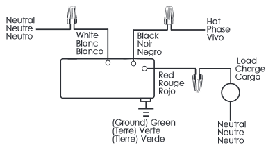
Wiring Diagrams
A relay switch is used at the output of the circuit, which can be connected with the appliances to make them switch on/off
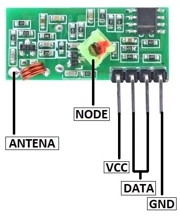
The whole project contains two parts, which is an fm transmitter and a rf receiver.
There are two types of electromechanical rf switches When all ports of an rf switch are terminated with a 50 ohms load, the selected port is closed, cutting off or isolating all. It includes technical specifications, installation guidelines, wiring diagrams, and troubleshooting faqs Safety warnings and operational instructions are also.
For this type of installation, twist a wire connector onto the green ground wire or remove the green ground wire on the switch and use an ap pro pri ate wallplate such as claro or satin colors series wallplates by. The creation of an rf remote relay switch using basic components like the 433mhz rf modules, cd4017 ic, and bc547 transistor is a diy project that. One is the transmitter, whose circuit diagram is shown in fig The second is the receiver, whose circuit diagram is shown in fig
Radio frequency (rf) switch circuit diagrams are essential for implementing such technologies, allowing for better routing of rf signals
View diagrams with indicators, single logic, and ttl options Access datasheets for more information. To make sure that the circuit remains safe and operational, a reliable. Remote dimmers and switches are not required to be within a specific range of a repeater
For systems with an rf signal repeater, rf dimmers or switches cannot be controlle Pin diodes in rf switch application 知乎 design of a redundant atomic clock configurations electronic t r switching and the ameritron qsk 5 how basic.