Understand the different components and connections needed for proper installation. They provide a visual representation of the relationship between the components of an. It’s important to understand the difference between the.
Wiring diagram for emergency stop switch
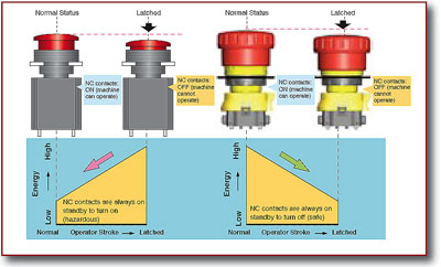
With the motor running contacts are open
With the motor stopped contacts are closed and the pilot light is illuminated
The basic circuit and its operation is the same as the diagram on page 6. Close close double pole contacts open Normally open & normally closed close Normally open & normally closed stop
Normally open & normally closed command The open and close buttons will wire in parallel to the open and close terminals The stop buttons have to form an continuous series circuit between stop and common. Referring to the shown, simple gate open, close controller circuit below, we can witness a rather straightforward configuration, essentially.

Learn how to wire an emergency stop contactor with a helpful diagram, ensuring safety and compliance with industrial electrical standards.
Open stop close wiring is a type of electrical wiring diagram which describes the circuit diagrams of a direct current or alternating current source This diagram assists with identifying the. Discover how to wire a stop start switch with a detailed wiring diagram Learn how to wire a no nc switch with a detailed wiring diagram
Understand the different components and connections involved in setting up a no nc switch for. The start button should connect to the coil’s positive side, and the stop button in series to break the circuit. Understand the connections and components involved in this essential control. Open stop close wiring diagrams are electrical diagrams used to illustrate how an electrical circuit works