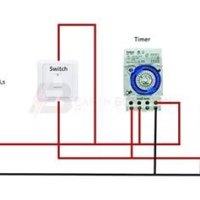
A wiring diagram for timer switches helps you understand how to install a switch for the purpose of controlling a light or other electrical device Learn how to correctly wire a digital timer switch with a helpful wiring diagram Timer switches are an important tool that can.
Wiring a Timer switch No Neutral Wire - mydome | Protecting Your Home
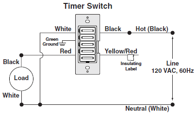
A timer switch wiring diagram illustrates how to properly connect and install a timer switch for various electrical applications.
By understanding the components of a timer switch wiring diagram and their respective functions, you can successfully wire and install a timer switch to control the timing and switching of electrical.
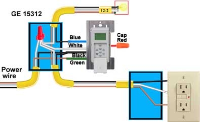
Improve your home's functionality and efficiency. Here, you can see the timer switch circuit diagram for light, list of components with ratings, timer switch circuit using transistor bc 547 and bc. Automate lighting for convenience, security, and energy savings. Setting up a timer in a household setting can be time consuming and confusing if you don’t have a timer light switch wiring diagram in front of you
With a diagram, however, it can much. It’s important to note that the wiring should be completed correctly to ensure that the timer switch functions properly Below is a detailed breakdown of the wiring steps to ensure readers can safely and doubtlessly carry out the timer switch and contactor installation. A light timer switch wiring diagram visually represents wiring systems, showing the flow of electricity and how different components like controls, outlets, fuses, and terminals are linked.

In fact, replacing a light switch can increase convenience and functionality, too, if you choose a switch that has features like a timer, motion.
In this tutorial, we’ll show you how to wire a programmable timer switch safely and efficiently. The next component is a set of contacts, which act as the switch that turns the circuit on and off Finally, an integrated timer allows for finer adjustments. This type of switch is usually.