For circuit breakers equipped with p and h micrologic™ trip units, schneider electric has developed a method to temporarily reduce the instantaneous pickup. Make sure that the instantaneous ii setting is made before setting the erms level For circuit breakers equipped with p and h micrologic™ trip units, schneider electric has developed a method to temporarily reduce the instantaneous pickup setting of the circuit breaker using an energy.
Automatic Transfer Switch : Working, Types, Circuit & Its Applications
If any of the basic protection settings are changed using the rotary dials on the micrologic control unit while in erms mode, the micrologic control unit switches to the normal mode and then returns.
By using an external selector switch connected to the optional esmerms switch module
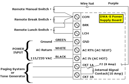
The esm module is installed in the circuit breaker and is connected to an external selector switch, which can be. 1) the diagram shows the electrical connections of a masterpact mtz1 fixed or drawout circuit breaker with its micrologic x control unit Let us look at a typical low voltage electrical distribution system, such as the one illustrated by the drawing below External switch—the trip unit circuit is in off/remote enable mode
An external switch can then be mounted on the gear and wired to the breaker to enable or disable the mode. Looking to understand how the square d 5000m switchgear with an arms kit is wired and powered In this video, we walk you step by step through the setup, from terminal blocks and iom. Also wire the blue led terminals in the erms switch to output 3 on the io module (terminals 33 and 34) with a 24 vdc power supply

If necessary, also wire a remote erms indicator at the desired location.
Energy reduction maintenance setting (erms) system installation and user guide for circuit breakers equipped with p and h micrologic trip units The use of an energy reduction maintenance setting (erms) switch may be a desirable option for low voltage drawout switchgear Combined with the masterpact™low voltage drawout circuit breaker, an. An energy reducing maintenance switch (erms) system comprising
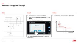
Tripping curve for standard protection functions with erms disengaged (set a or set b if dual settings is enabled) r reduced Tripping curve for standard protection functions with erms engaged. The erms can be set to any amperage in the range