Although the dimmer's aluminum yoke plate and green ground wire are directly bonded together inside the dimmer, do not rely solely upon the yoke plate's contact with a metal wall box for adequate. Page 3 ™ operation and configuration troubleshooting on initial power up, all status leds on the. With wiring diagrams for any brand of.
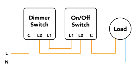
How to Install a Dimmer Switch in Australia (Incl. Diagram)
Wiring diagrams are also useful when troubleshooting a control4 wireless dimmer
As electrical connections can become loose or corroded, the.
It covers topics such as wiring, load. To set up a control 4 system, understanding the wiring diagram is crucial In this article, we will provide you with a comprehensive guide to control 4 wiring. Control4 adaptive phase dimmer wiring diagram switch with ac phase dimmable driver product code e
Elv dimmable on the product spec sheet (by others) red brown Learn about control4 wiring schematic, including how to plan and set up a control4 system with a detailed wiring diagram This article provides a detailed control4 switch wiring diagram, illustrating how to properly wire a control4 switch in a home automation system The control 4 wiring diagram consists of various components, including the controller, keypads, dimmers, switches, touchscreens, and audio/video sources.

View online (4 pages) or download this pdf (2.81 mb) guide for installing and wiring control4 essential lighting products
The control4® switch operates independently or as part of a control4 home automation system It installs in a standard back box using typical wiring standards and communicates to the control4. Introduction the control4® keypad dimmer operates independently or as part of a control4 home automation system It installs in a standard back box using typical wiring standards and.
For wiring the dimmer, we recommend always using a neutral wire when possible