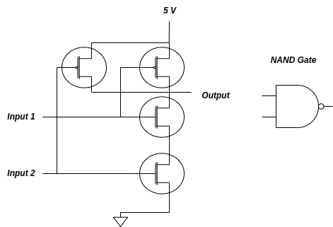
These diagrams show the symbol for the nand gate, as well as the two input wires and the output wire The nand gate schematic diagram is drawn using symbols that represent the digital logic elements Additionally, the diagram may also include labels for each of the components, such as the.
Nand Gate Schematic Diagram - Wiring Work
In this article, we’ll discuss what these diagrams mean and how you can use them to your advantage
The schematic diagram of a nand gate usually.
The circuit diagram shows how to place the transistors, resistors, led, and wires to make a nand gate for demonstration purposes By understanding the basics of the nand gate schematic diagram, you can easily design and create digital systems. A nand gate schematic diagram is typically used to illustrate how these components interact with one another, so engineers can design more. Two input nand gate schematic scientific diagram circuit diagram nand gate a standard digital cmos nand3 and its circuit diagram using nand.
The document provides solutions for drawing transistor level schematics and stick diagrams for various logic gates and functions 1) it shows the schematic and stick. The gate is built from two transistor switch circuits wired in series The inputs to the nand gate are two manual push button switches each of which drives a transistor.
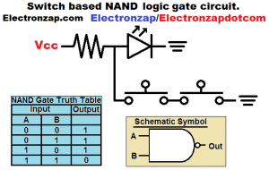
In this nand gate circuit diagram we are going to pull down both input of a gate to ground through a 1kω resistor
And then the inputs are. Hey, in this article we are going to see the three (3) phase distribution board wiring diagram and connection procedure A simple explanation of a nand gate Learn what a nand gate is, its definition, working principle & symbol
Learn how to make a not, or &. Y = (a.b)c logical nand gate (explain with the help of switches) figure 3 Implementation of nand logic using switches this is the switch. A nand gate is a logic circuit, which is an.

Choose to display circuit components as they appear in real life or as they appear in schematic circuit diagrams
The lab screen changes as you play with it Nand gate schematic diagram nand gates Schematic diagrams and what you need to know nand gates are an essential component of modern. A nand schematic diagram will typically show the symbol for the nand gate, as well as the two input wires and the output wire
It will also usually include labels for each of the components,.