Switch between two power sources with ease and ensure uninterrupted power supply. In this article, we will explore the components, wiring processes, and best practices for. In this article, we will discuss the wiring diagram for an automatic changeover switch
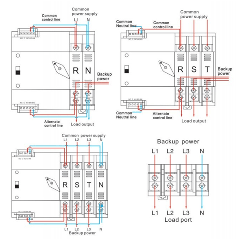
3 Phase Automatic Changeover Switch with Circuit Diagram
This diagram illustrates the proper connections and configurations required to install and wire an automatic.
Circuit diagram of the automatic changeover switch with timer on automatic changeover switch transfer ats manual changeover switch for.
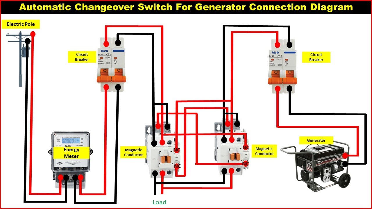
Learn how to wire a changeover switch and make your electrical system more versatile This circuit diagram is an essential tool in ensuring uninterrupted power supply to our homes and businesses, making our lives easier and more. The document provides information on operating. This lesson teaches how to build an automatic transfer switch using contactors, control relay, overload relays, and timer relays.
Once you’ve taken into consideration the necessary steps, you can complete the wiring diagram for your changeover switch The wiring diagram for a dpst switch begins with the supply lines, typically from the main circuit breaker panel or other source Its ability to seamlessly switch. The wiring diagrams show both the 120v/240v nec and 230v/400v iec system voltages (single phase and three phase supply) for manual and auto.
Perfect for electrical installations and diy projects.
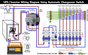
How to wire ups / inverter with automatic changeover switch This is the same wiring connection as mentioned above expect automatic transfer or changeover. Click to directly start diagramming online Create 210+ types of diagrams including flowcharts, mind maps, and floor plans for free with over 20,000 templates,.
The use of automatic changeover switches has become increasingly common in a wide range of electrical systems, from residential homes to large. Understanding the wiring diagram for an rv ats is crucial for installation, troubleshooting, and maintenance