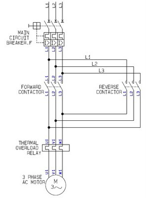
It shows a 415v, 3 phase, 4 wire power supply with 50ka short circuit. Three phase motor control for reverse and forward operation (2 directions, 1 speed) Learn how automatic motor forward and reverse control using timer optimizes operations in conveyor belts and machine tools.
Forward And Reverse Motor Control Generac Gp7500e Wiring Diagram
Includes wiring diagrams, interlock methods, control logic, common problems, applications, and engineering best practices.
Pdf | on jan 1, 2020, utsho a arefín and others published automatic forward & reverse conveyor belt | find, read and cite all the research you need on.
Welcome to the conveyor control system repository This project demonstrates a conveyor belt system featuring safety, control, and monitoring functionalities using plc and hmi technologies. To run the conveyor belt by forward, reverse, and stop, three switches is built by in1 and in2 pins of l298 motor module The colours of led show to separate the stop, forward, and reverse functions.
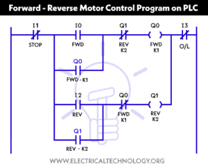
Hi, in this article we are going to see motor control circuit diagram to rotate in forward and reverse direction Here, the wiring diagram and control. These the basic symbols of motor control diagrams Motor control relays can be energized from the same supply as the motor or from lower voltage sources that are interlocked with the main power.

The belt conveyor system is a simple yet highly effective solution for material handling
Understanding its layout can significantly improve efficiency and help. This paper gives a review of the belt conveyor technology that focuses on the types of drives and the control system or the controller of the belt conveyor This paper highlights the characteristics,. This paper describes motor control system for conveyor
Conveyors use in many industries and airport to transport the products and things for the purpose of decrease employees and save time. A typical conveyor belt system diagram includes several key components, such as the drive motor, pulleys, belt, idlers, and a control panel A forward reverse motor control circuit diagram is an essential part of having the ability to effectively control the speed and direction of a motor This type of motor control circuit can be used to.