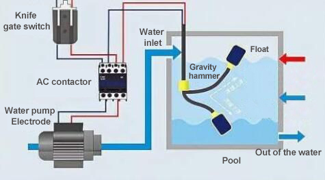
Wiring diagram for float switch The float switch wiring diagram typically includes symbols that represent the different components in the circuit, such as the float switch, power source, control panel, and pump. Learn how to correctly wire a float switch for various applications, including pump control and water level monitoring systems.
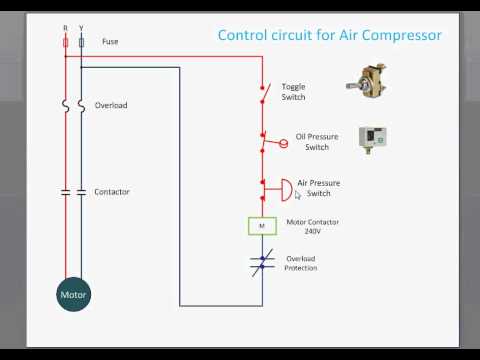
Air compressor wiring diagram air compressor – Artofit
Learn how to wire a float switch
A float switch is a mechanical switch used to determine the liquid level in a tank.
With level switches, these circuits are opened and closed by the float either moving up or down based on the rising or falling level of the liquid Collect relevant installation manuals and guidelines provided by the manufacturer for the float type level switch, including wiring and mounting. The float switch schematic diagram provides details about the electrical components required to complete the installation, including a power. Learn how to wire a float switch to a solenoid valve for automatic fluid control
Learn how to wire a float switch with a diagram This guide will help you understand the installation process and ensure proper functionality. The power circuit supplies electrical power to start and run the motor, while the safety circuit protects from overheating When wiring an air compressor,.
How to connect / wire a/c float safety switchthis safety switch will prevent your ac unit from flooding your house.#ac #acfloatswitch @amazon #floatswitch.
Learn how to wire an air compressor with both manual and automatic control systems in this detailed tutorial Whether you're an electrician, technician, or a diy enthusiast, this video breaks down. A wiring diagram is a visual representation of the electrical connections and components of an air compressor Learn how to read and understand wiring.
Whether you're looking to install a float switch for a water. Stable grounding reduces the risk of electric shock and protects control components during voltage spikes Air compressor circuit diagram with motor pressure switch and power connections connect. To work properly and safely, air compressors require precise control

That's why they contain an intricate system of switches, sensors, solenoids, and.