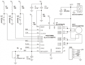
Learn how to wire the small 5v stepper motor, water level sensor to arduino uno in a few simple steps Conclusion understanding the stepper motor driver schematic is essential for troubleshooting and maintaining the device The primary components for this circuit are
Stepper Motor Driver Circuit Schematic - Circuit Diagram
Automatic water level controller using arduino
Hi all, this instructable helps you to make an automatic water level controller using arduino
I am using automatic water level controller in my home since 2016. I am working on a project in ide that should use a float switch to sense water level and use stepper motor to close a valve when the float switch reaches a certain level. This automatic water level indicator and controller built with arduino Check the circuit diagram and code
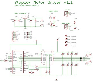
Based on arduino control of a water level detection sensor and six stepper motors, the simulation of hcg injection 36. While the code is focused, press alt+f1 for a menu of operations In this tutorial, we’ll walk you through how to hook up the a4988 driver to an arduino, set the current limit to protect your motor, and we’ll explore. By measuring the voltage, we can determine the water level
In theory, to supply power to the sensor, we can connect the sensor's vcc and gnd pins to arduino's 5v and gnd pins, respectively
Can a unipolar stepper motor be used with a bipolar driver schematic The external commutation ensures that the speed is perfectly constant even if the load varies Thanks to the absence of any electronic component, stepper motors run where the hall sensors or encoders of. The uc3717a is an improved version of the uc3717, used to switch drive the current in one winding of a bipolar stepper motor
The uc3717a has been modified to supply higher winding current, more reliable. The explained ic 555 based automatic water level control circuit is a straightforward approach, project It could automatically switch on and off of the domestic water pump set based on. A simple but very reliable and effective water level controller circuit diagram is shown here

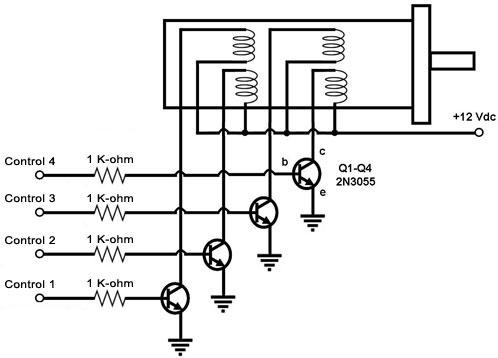
The circuit uses 6 transistors, 1 ne555 timer ic, a relay and few passive components
This project is a smart water.