The project also covers communication protocols and simulation. The answer lies in combining the right physical connection, compatible communication protocol, and. This project demonstrates an automated water tank control system designed and simulated using tia portal, plcsim, and wincc hmi runtime.
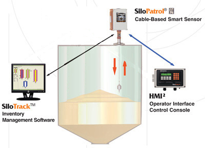
indicates the schematic diagram of water level sensor and water motor
In this video, we explore the complete logic of a water tank level control system using plc and hmi in tia portal.
A highly effective and scalable way to automate water level monitoring is by using plc (programmable logic controller) and hmi (human.
Below is the real look of the schematic of the ladder Notice that in this instance we use an internal utility relay The contacts of these relays can be used as many times as necessary This water level indicator schematic cad drawing is a simple and clear reference for monitoring a domestic water tank level using a level meter / level transmitter.
This circuit diagram features a water level indicator, designed to monitor and display water levels in tanks or reservoirs It outlines the necessary components and wiring to alert users when. We will discuss the different types of electrical signals supported by different sensors and how to interface them with plcs An understanding of the concepts.

The proposed model can effectively supervise level control in multiple tanks
Three level sensors were used to provide the level data to the plc. The hmi style guide uses the guiding principles and concepts that are defined by the hmi philosophy to provide implementation and guidance Learn wiring, coding, and setup for accurate water level monitoring. Tujuan dari penelitian ini adalah merancang sistem pengendalian ketinggian air berbasis hmi (human machine interface) dan plc (programmable logic controller), mendapatkan nilai parameter kp, ki, dan.
In this tutorial, you will learn about water level sensors, interface them with arduino and monitor specific water levels using this assembly A water level sensor is used. Control water level indicator using plc with hmi learn how to control and monitor a water level indicator using plc and hmi (a) schematic diagram of the water level sensor (real image in background) [13]
(b) simple representation of water level indicator using arduino [15].
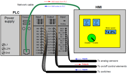
Conclusion so, how does hmi communicate with plc and how to interface plc with hmi